Air Valves in WaterGEMS and WaterCAD
An Air Valve is the model element used to represent air relief valves, air release valves, vacuum breaker valves and combination air valves. The underlying behavior of the valves is to be closed when then hydraulic grade is above the valve elevation and to open to maintain atmospheric pressure when the hydraulic grade would otherwise have dropped below the valve.
While they are useful in normal operation, they are especially important in transient analysis (available in Bentley HAMMER). See the help for air valves in HAMMER. They are also used in filling and draining of pipelines which is not addressed in WaterGEMS/CAD.
While air valves are often placed on pumps to remove air, their primary use is at high points in pressure piping systems, which are the first locations which can experience negative pressure in water systems and are the most likely places where air can accumulate.
In water distribution systems which must maintain a positive pressure, the valves are almost always closed. In sewer force mains, irrigation systems and raw water transmission systems, pressure can drop when pumps turn off or head loss becomes excessive and they can often be in the open position and pipes can be partly full, immediately downstream of the high point.
Because air valves can change status during a model run, they can introduce instability in the run. The more air valves, the more likely this is to occur. In systems with multiple valves, it is best to focus the analysis on those valves which are likely to open and close. The valves that are almost certain to remain closed in the analysis can have a property "Treat as Junction?" set to True and the air valve will behave as a junction node in the model run. For valves being analyzed, this property should be set to False. The "Treat as Junction" property is the only property in steady and EPS runs that is different between a junction and an air valve. For transient analysis (available in Bentley HAMMER), there are numerous other properties that can come into play.
If there is no air valve at a high point and the pressure drops below zero, the pipeline will behave as a siphon. This is generally not recommended as flexible pipes may collapse and intrusion of questionable fluids can occur in water distribution systems. WaterGEMS/CAD provides a warning message if the pressure drops below zero and a more severe warning when it drops below the vapor pressure of the fluid (32 ft, 9.8 m for water). A value less than the vapor pressure indicates that no flow will occur.
The behavior of air valves can be best viewed using a profile view. With no air valve, the profile of a siphon would look like the figure below with the hydraulic grade below the node level.

With an air valve in place, the valve would prevent the negative pressure by opening to atmosphere. There may be partially full flow downstream of the high point (where the hydraulic grade line is below the pipe). The location where the hydraulic grade line crosses back over the pipe is the location where full pipe flow is restored.

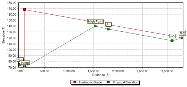
In most cases, when the pump is operating, the hydraulic grade line will remain above the pipe and the air valve will be closed.
When the pump or other source on the upstream side of the high point is shut off or closed, the pipe generally remains full. However, the WaterGEMS/CAD profile will not reflect this and warning messages in user notifications identify the elements which are no longer connected to a source. If display of an accurate hydraulic grade during these times is important, then the model can be made to display the line correctly by inserting a reservoir with a water elevation equal to the elevation of the air valve and connect it to a node immediately upstream of the high point with a very small pipe which will carry essentially no flow. This will result in a display a flat hydraulic grade between the high point and shut off pump.
If the user is having trouble getting a model with air valves to balance, it is best to set all the air valves to Treat as Junction = True and see if it is the air valves that are causing the problem. Then turn valves on (Treat as Junction = False) one-by-one to see the effects.